Repair and restoration of retro consoles, 8 bit computers. In this blog I hope to show you how to repair, retrore and modify old consoles and handhelds, from manufacturers such as Atari Amstrad Acorn Sinclair Commodore Dragon Sony MSX BBC Playstation Sega Microsoft xbox Spectrum ZX81 Vic 20 VIC20 C64 Amiga Binatone Grandstand.
Apologies for the delay with this entry; varied reasons include school holidays, two birthdays and some minor repairs of some retro console birthday gifts! Please feel free to use my PCB and 3D printed housing designs found on my Github and Thingiverse should you wish to make your own joystick adapter. Here is the TI994a working with the FlashRom99 and my Joystick Adapter circuit. Here are all the components required for this mod. The gerber files for my PCB design can be found on my Github. https://github.com/Alleged-Geek/TI99-4a-Joystick-Adapter/ And you are looking for the zip file named below if you are going to send the gerber file off to be manufactured. ti99-4a-adapter_2022-07-27.zip My github also contains stl files for printing the housing. And here is my version of the schematic diagram. You will need 10 X IN4148 signal diodes which can be found on eBay. 1 X DB9 D-SUB 9 Pin Female connector, again found on eBay. 2 X DB9 D-SUB 9 Pin Male connector al...
Get link
Facebook
X
Pinterest
Email
Other Apps
TI99/4a PAL Composite Video Mod for the PHA 2036 Modulator
This
modification only works on the PHA 2036 Modulator (the metal cased modulator)
There is a tutorial available on the TI-99 Italian UserClub Website should you happen to have the plastic PHA 2030
modulator.
www.ti99iuc.it
Many thanks goes out to Sergio
Vigano and the TI-99 Italian User Club for making this modification public.
My TI99/4a had a reasonable picture
on my modern TV using the RF cable; it was quitter stable and the colours were
pretty good as well. But as I am planning to restore and upgrade the classic
computer I decided that I would try my hand at the composite video mod found in
the link above.
The website is excellent, it has
clear and easy to follow instructions and I did think about doing the
modification exactly as shown on the site. But then I decided to try and
improve the mod a little bit, so I ordered some parts from Amazon and eBay.
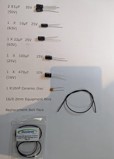
I have included screenshots of the
exact parts I ordered for this mod during the clip.
I wanted to try and keep the
modulator looking as close to the original as possible and decided that I would
order a 4 pole 3.5mm chassis mount socket and a 3.5mm to RCA cable so that I
could connect it to the TV using a standard SCART adapter.
I also decided to mount the socket
out of the same side of the modulator as the RF socket is on.
As far as modifications go, this one
was pretty easy but it does require some tooling which you may not have such as
a drill. There is another procedure for this mod available on the TI-99 Italian
User Club which requires less tooling.
Tools required:
Cutters
Pliers
Soldering Iron
Powered Drill (with stand if
possible)
Shifting Spanner
Tweezers
Heatgun
Tapered Reamer (only if you don’t have
an 8.5mm drill bit)
3mm HSS Drill Bit
8.5mm HSS Drill Bit
Flat Headed Screwdriver
Components required:
4 pole 3.5mm chassis mount socket
4 pole 3.5mm jack plug to RCA
connectors cable (I would reccomend about 2M in length)
1.5mm Heatshrink Sleeving
3mm Heatshrink Sleeving (or cable
ties)
Around 300mm of the following
colours of 7/0.2mm equipment wire
Black
Yellow
White
I found the
4 pole 3.5mm chassis mount socket in Amazon; see picture below for the exact
one I ordered.
And the RCA
cable from eBay; I had bought a small 0.5M cable for another project so used
this smaller cable during the modification. I have since bought a longer 2M
cable which was actually cheaper than the 0.5M cable!
Before we
start this mod, you need to determine if the TI99/4a’s modulator is the correct
version for this type of mod.
Below is a
picture of the correct modulator.
Let’s have
a look inside the modulator and figure out the best place to fit the socket.
Remove the
two small case screws on the modulator with a small flat bladed screwdriver.
Below is a
picture of the inside of the modulator and my proposed location for the 4 pole
socket.
I chose
this location for a couple of reasons:
1I
could have drilled the hole to the right side of the modulator as shown in the
tutorial in the TI-99 Italian User Club but upon inspection I found that
fitting the connector there would be difficult due to the length of the
connector.
2I
wanted the cable to come out on the same side as the original RF cable.
3I
wanted to drill the hole with the minimum chance of damaging any of the
components inside the modulator such as the variable capacitor highlighted
below.
So after
some careful measurements I found that if I drilled the hole 60mm from the left
of the modulator and 15mm from the top, this would ensure that I would have
little risk in damaging any of the components.
Measure and
mark the case with a permanent marker (use IPA to remove the ink afterwards)
Then punch
the location of the hole with a centre punch (if you have one) I didn’t have my
one to hand for this mod so I carefully scored the hole location with a
scalpel.
Measure the
connector to determine the correct hole size; the data sheet said that the
threaded end of the connector was M8 but I decided to measure for myself just
in case using my vernier callipers.
After
reading the callipers I decided that an 8.5mm hole would suit but as my drill
bit set only went up to 6.5mm, I would have to use a tapered reamer to enlarge
the hole further from the 6.5mm.
Then drill
the hole; I got to try out my new drill press stand for this (but if you are
careful use a standard powered drill or hand drill) I found that the best way
to hold the modulator in my vice was to refit the lid of the modulator.
As a 6.5mm
hole is quite large, it is best to drill a pilot hole; this would help avoid
any wobbling of the drill bit on the modulator. I opted to use a 3mm HSS drill
bit for this.
Fit the 3mm
drill bit to the drill and set the depth to drill the hole just below the metal
plate of the modulator; this would also reduce the chance of damaging any of
the components inside the modulator.
Drill the
pilot hole then enlarge it with either an 8.5mm drill bit or in my case a 6.5mm
drill bit. On a safety note, please wear safety glasses whilst doing this!
Once
drilled, I used a tapered reamer to gradually enlarge the hole; note that I
opened up the modulator again to ensure that the tapered reamer didn’t cause
any damage to the electronics.
Ideally,
the connector should be a tight fit but you do not want to have it too tight as
you will risk damaging the plastic thread on the connector.
Once the
socket fits snugly, remove any sharp edges caused by the drill with a file on
the inside of the modulator and if needed use a de-burring tool on the outside
of the modulator.
Now it is
easier to solder the wires on the socket before fitting it to the chassis of
the modulator but I wanted to double check the connections from the socket to
the RCA cable so I dug out my multimeter and did some continuity tests.
The photo
below shows the connections of the socket taken from the manufacturer’s data
sheet.
However, I
found that after testing, the actual pinout for the socket to RCA cable was as
shown below.
Below is my
wiring diagram for the socket; you will see that I have linked pins 1 and 2
together. Some modern TV’s will automatically put sound to both speakers when
it only has a mono input but in case either of my Geek TV’s didn’t I decided to
link pins 1 and 2 together which should ensure that both speakers get the same
audio from the mono feed from the TI99.
For wiring
up the socket to the modulator I used three 300mm lengths of 7/0.2mm equipment
wire. For the Video Pin, I decided to use Yellow, for the GND, I used Black and
for the Audio, I decided to use white instead or Red as I usually only use red
for a positive DC Voltage wiring.
Now with
the socket in the helping hands, strip twist and tin 5mm of insulation from the
Black and Yellow wires.
As we are
going to link pins 1 and 2 together, strip twist and tin about 10mm of insulation
from the white wire.
Now place
the stripped black wire through the small hole on Pin 4 of the socket and
solder it; I find the easiest way to keep the wire in place is to use a pair of
cutters or pliers to put tension on the wire as shown below.
Then repeat
the process for the Yellow wire on Pin 3 of the socket.
Now make an
‘L’ shape with the white wire with the tinned part bent over at a right angle
from the insulation. Solder the tinned part on to Pin 2 and bend the excess
tinned wire over to pin 1 and solder it.
Trim the
excess tinned wires away from the socket.
Cut 2 15mm
lengths of 1.5mm heatshrink sleeving and fit over the Yellow and black wires;
ensure that no exposed conductors are showing then shrink the sleeving with a
heatgun.
And you
should have a socket with the wires coming from the pins looking like this.
Now fit the
socket to the chassis of the modulator; I used a shifting spanner to tighten
the nut which reduces the risk of scratching the black paint on the chassis.
Now cut 4
10mm lengths of heatshrink sleeving; I prefer to use heatshrink sleeving in
place of cable ties to group the wires as I think that it looks neater.
Then route
the wires as shown below, fit the sleeving and shrink it down with a heatgun.
Now solder
the Black, Yellow and white wires on to the following positions as shown in the
picture below.
It is a
good idea to tin each position before soldering the wires on to them; this is
quite fiddly for pins 3 and 4 of the modulator due to its close proximity to
the chassis.
Cut the
Black wire to length.
Strip,
twist and tin 5mm insulation from the Black wire.
Then solder
the black wire on to position 3 on the modulator.
Fitting the
Yellow wire to Pin 4 is exactly the same process, cut the wire to length,
strip, twist and tin 5mm insulation and solder it on to position 4.
I found it
easier to use tweezers to hold the wire in place when soldering the yellow
wire.
Now cut the
White wire to length, strip twist and tin 5mm insulation and solder it on to
the lower leg of the 330Ω resistor as shown in the earlier
wiring diagram.
And you
should have a modulator looking like this.
Reassemble
the Modulator.
Then hook
up your TI99 to a SCART adapter on your TV or monitor.
And test!
This works perfectly! Again, many
thanks to Sergio Vigano and the TI-99 Italian User Club for making this
modification public.
Below is my youTube clip of the
whole process from start to finish.
I hope that you have found this
useful.
If you have any questions or queries
about this mod then please feel free to leave a comment or email me directly at
alleged_geek@aol.com
Thank you for taking the time to
read this entry, the next in my TI99/4a series is a complete Re-Cap of both the
Motherboard and Power Supply PCB’s


Comments
Post a Comment