TI99/4a Joystick Adapter (with 3D printed housing) and a FlashROM 99 Installation
Apologies for the delay with this entry; varied reasons
include school holidays, two birthdays and some minor repairs of some retro
console birthday gifts!
Please feel free to use my PCB and 3D printed housing designs found on my Github and Thingiverse should you wish to make your own joystick adapter.
Here is the TI994a working with the FlashRom99 and my
Joystick Adapter circuit.

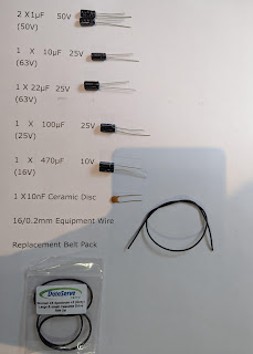
Here are all the components required for this mod.

The gerber files for my PCB design can be found on my
Github.

https://github.com/Alleged-Geek/TI99-4a-Joystick-Adapter/
And you are looking for the zip file named below if you
are going to send the gerber file off to be manufactured.
ti99-4a-adapter_2022-07-27.zip
My github also contains stl files for printing the
housing.
And here is my version of the schematic diagram.

You will need 10 X IN4148 signal diodes which can be
found on eBay.

1 X DB9 D-SUB 9 Pin Female connector, again found on
eBay.

2 X DB9 D-SUB 9 Pin Male connector also found on eBay.

The 3D printed housing can be found here and on my
Github.
www.thingiverse.com/thing:5442911

Here are some pictures of the my
Solidworks design.


A FlashRom99, which can be found on eBay for around £30.

I am using my prototype PCB here; it is exactly the same as the PCB I also ordered from JLPCB. Below are some pictures of the prototype I used and the JLPCB ones I purchased.


As you can see, the JLPCB circuit boards have a solder mask and a silkscreen to assist you with the population of the PCB.
Below is a picture of a quote from JLPBC for the
circuit boards. The minimum quantity is 5 and the quote of £4.39 included all 5
PCB’s manufactured and as well as delivery!

Charlesd916 designed a fantastic housing for the
Flashrom99
https://www.thingiverse.com/thing:2021930
Many thanks Charles!

Now let’s get to work assembling the joystick adapter!
Start by bending the Diodes into a staple shape using a
pair of pliers.

It should be noted that the diodes require to be fitted
in the correct orientation.
Below is a picture for the correct orientation for the
diodes.

Fit D1 as shown in the picture below.

Below I am fitting it to my prototype PCB.

Then bend the legs out by 45° to prevent the diode from
moving when soldering.

Now you could solder each diode individually but I
decided to fit D1 – D5 then solder all 5 at the same time.
This is quite easy to do as the diodes are all in line
with each other. However, I would strongly recommend that you do not also fit
D6 – D10 at this point as the legs of all 10 diodes will get in the way of your
soldering iron.

Below is a picture of D1 – D5 fitted and ready for
soldering on my prototype PCB.

Now solder the Diodes.
When soldering, you will require to heat both the
component leg and via on the PCB to a temperature warm enough to melt solder.
Typically this takes from 1 – 3 seconds with a soldering iron set at 330°C (for
leaded solder) if you are using lead free solder you will require to have a
higher temperature set on your soldering iron.
Once the leg and via are warm enough to melt solder,
feed solder on to the via and component leg. The solder should melt and rise up
the leg of the component. Again this typically takes from 1 – 3 seconds.

Once all 5 diodes have been soldered, trim the legs of
the diodes just above the solder joint as cutting into the solder will weaken the
joint.

Then repeat the process for diodes D6 – D10, note that
the cathodes face towards the outside of the PCB as shown in the picture below.

Now it is time to fit and solder the 9 pin D-SUB female
connector.
In order for this to fit on to your TI99/4a you will
have to remove the metal faceplate.

This is easily done by removing the 2 threaded locking
nuts.

Then the faceplate should simply lift off.

Fit the D-SUB socket on to the PCB as shown below.

I would recommend soldering two opposite legs of the
connector first before soldering all 9 pins as this will make seating the
connector flat on to the PCB a lot easier should it not be seated correctly. If
it is not flat against the PCB it is an easy job to heat the leg on the raised
side (or sides) and simply push the connector flat against the PCB when the solder
is molten.

Once the connector is seated correctly, solder the
remaining 7 pins.

Now fit the two 9 pin D-SUB male connectors. There is
no need to remove the metal faceplate for these connectors and it is recommended
not to do so as the joysticks will fit better with the faceplates intact.

As before, solder the two opposite pins of the
connectors before checking that they are seated flat against the PCB. If they
are seated correctly, solder the remaining pins.

I would recommend soldering the 4 metal fixing clips
either side of the connectors as this will improve the physical strength and stability
of the connectors.

Now assemble the Joystick adapter into the 3D printed housing. I printed this housing using my Anycubic Photon resin printer which prints beautifully smooth surfaces. But you could also use a filament printer for this.

Fit the PCB on to the top half of the housing as shown below.

Then fit the bottom and screw it together with some
16mm M3 self-tapping screws.

And you should have something looking like this.

Now it is time to assemble the FlashROM 99 into the 3D
printed housing I found on Thingiverse.
I opted to use my filament printer for this for a
couple of reasons… In truth I could only use my filament printer for this as it
was too large for my resin printer (although I do have access to a larger resin
printer). The other reason is that resin prints are quite brittle and as the
FlashROM 99 is a snug fit into the housing I got the feeling that I would break
the housing should I try to fit it into a resin print.
Below is a picture of the 3D printed housing and
FlashROM 99.

Fit the FlashROM99 PCB into the main 3D print. This is
a very tight fit and was pretty awkward in truth. Be very careful not to lever
the PCB into the housing using the SD Card Reader socket as this is a weak
point and could easily be damaged.

After much levering, pushing and pulling the FlashROM
99 PCB finally snapped into place!


Fit the lid then prepare the software on to a full sized SD card.
For this I used an 8GB micro SD card with a full sized
adapter formatted at FAT32.
The good folks at Atari Age have a thread containing links for TI99/4a software.

To make things even better OOWReX has even put together
his collection of software for the TI99/4a and bundled it all up in a Zip file…
Many thanks Shane!
You can download that by accessing the AtariAge forum
using this link.
https//forums.atariage.com/topic/254953-flashrom99-16k-images/?tab=comments#comment-3578333
All the software in his Zip file will work on a TI99/4a
without the 32k RAM extension.
Simply download the zip file and transfer it on to the
root of the SD card.
Now Set up the TI99/4a.
Firstly plug in the FlashROM99 cart as shown below.

Then plug in the Joystick adapter.

Now connect your Atari type sticks.

Now turn on the TI99/4a.

Hopefully you will get the boot screen as shown below.

Pressing any key should bring up this menu.

Press ‘2’ to enter the FlashROM99 menu and hopefully
you will be greeted with this on screen.

Use the < or > keys to navigate the folders and find the software you wish
to run. In my case I wanted to try Burger Builder.
And press the letter of your game of choice. The software
should load almost instantly!

Then enjoy! I had never played this game before and was pleasantly surprised how good it was! Pity about my terrible gameplay though ;o)

A YouTube clip of this mod from start to finish can be
found below.
Thank you very much for taking the time to read this
entry… apologies for the delay in updating my blog!
If you have any questions or queries about this mod
then please feel free to leave a comment or email me directly at
Next up I am going to build a 32K Ram extension pack.

Comments
Post a Comment