Repair and restoration of retro consoles, 8 bit computers. In this blog I hope to show you how to repair, retrore and modify old consoles and handhelds, from manufacturers such as Atari Amstrad Acorn Sinclair Commodore Dragon Sony MSX BBC Playstation Sega Microsoft xbox Spectrum ZX81 Vic 20 VIC20 C64 Amiga Binatone Grandstand.
Apologies for the delay with this entry; varied reasons include school holidays, two birthdays and some minor repairs of some retro console birthday gifts! Please feel free to use my PCB and 3D printed housing designs found on my Github and Thingiverse should you wish to make your own joystick adapter. Here is the TI994a working with the FlashRom99 and my Joystick Adapter circuit. Here are all the components required for this mod. The gerber files for my PCB design can be found on my Github. https://github.com/Alleged-Geek/TI99-4a-Joystick-Adapter/ And you are looking for the zip file named below if you are going to send the gerber file off to be manufactured. ti99-4a-adapter_2022-07-27.zip My github also contains stl files for printing the housing. And here is my version of the schematic diagram. You will need 10 X IN4148 signal diodes which can be found on eBay. 1 X DB9 D-SUB 9 Pin Female connector, again found on eBay. 2 X DB9 D-SUB 9 Pin Male connector al...
Get link
Facebook
X
Pinterest
Email
Other Apps
‘External’ Internal SD2IEC Drive installation
And Killing my C16 in the Process!
Hello and apologies for the delay bringing you this
content; there are a couple of reasons but mostly due to a stubborn chest
infection which lasted over a month! The other reasons you will find out during
this entry.
For this entry, I would like to describe my idea behind
this mod. I have seen external SD2IEC drives out there on eBay and other sites
and they are reasonably priced but I decided that I would like something
slightly different.
I stumbled across a blog entry where someone had
installed his internal SD2IEC drive inside his C16 but although it works
flawlessly, I would like to have access to the SD Card Slot as well as having
status LED’s and the reset function button.
After a bit more research I found that someone had done
just that but at the cost of having to modify the case of his C16. Although it
did look good, I try and avoid destructively damaging any of my computers or
consoles wherever possible… I like to have the choice of returning everything
to its stock appearance.
So after a bit of measuring, I decided that I could fit
a 3D printed SD2IEC holder in the cartridge slot at the rear of the C16.
As there are a few different Internal SD2IEC drives out
there, I found one on eBay which appeared to be the smallest in size, so I
spent the £30 and ordered it.
The above photo is of the one I purchased from eBay
with the seller’s identity hidden.
When working on any of my computers or consoles, I buy
everything I plan to do to it at the very beginning then work out the order I
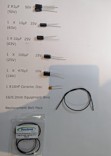
am going to modify the system. In the C16’s case, I bought the capacitors
required for the re-cap, the memory upgrade IC’s, heatsinks, the SD2IEC drive
as well as a JiffyDos kernel rom which I am planning to install next. I have
also bought connectors for a joystick converter which I am also planning to
write about.
The downside of this is that I have the parts sitting
in stock waiting to be installed and this was my downfall regarding the SD2IEC
drive. By the time I got round to installing it, I found that it was faulty… no
problem, all I had to do was write to the eBay seller and ask for advice to see
if there was anything I needed to do to get it working such as writing the
firmware etc…. right?
I had planned a full rant at this point but it was over
500 words long! So here are the main points:
I asked him politely for advice
He went on defence mode and was blunt to the point of
being rude; blaming me
I explained to him that he hadn’t sent it in an
anti-static bag
He still blamed me
I asked for a refund or replacement
He ignored me
I contacted eBay to complain but it had gone over the
31 days ‘warranty’
There was nothing I could do!
Now being an Aberdonian, you can probably imagine how I
felt about that… I think I even used some words which Mrs Geek taught me when I
made the Nickel Acetone ;o)
I am not going to name and shame the eBay seller over
the internet but if you are thinking about ordering an internal SD2IEC drive
from eBay, I will gladly let you know who he is through a personal message or
email.
Unfortunately that was only the start of my troubles
installing this modification!
I ordered an internal SD2IEC drive from TFW8B.com and
was delighted with the product and support documents. I have bought from them
before and have always been delighted with the quality of product and support
documents offered.
So I got to work designing my 3D Printed housing
sousing my Vernier callipers I measured the cartridge port at the rear of the
C16 and made my rough sketch on paper… apologies for the ‘rough’ rough sketch
After I had my initial design sketched out on paper, I
designed the 3D housing using Solidworks
I printed it out using my resin 3D printer
Then I populated the 3D Housing with the switches,
LED’s and SD2IEC drive.
As this mod blew up my C16, I am not going to go into
any detail about soldering everything together as I will cover that with the
redesigned housing.
But once fitted it looked like this.
I have to admit that it looked fantastic and worked
flawlessly but I made a couple of silly judgment of errors when designing and
testing the C16.
The first mistake I made was when I foolishly laid the
C16 on the carpeted floor for a prolonged test; this resulted in restricted air
flow getting into the C16 from the bottom slots on the C16.
My second mistake was not having any air holes or slots
on the 3D printed housing design. This as you can see blocked the large slot in
the rear of the C16 where air would usually enter or leave the C16.
This resulted with my C16 crashing after an hour or so.
I reset the C16 but was greeted with the black screen of death! I had killed my
C16! I was gutted!
I tried my Diagnostics Rom which didn’t even get past
the initial test; so I dug out my oscilloscope to have a look at the waveforms
on the usual suspects.
During my earlier mod when I re-capped the C16, I
placed heatsinks on the TED chip as well as the PLA chip which according to the
research I did were the two most commonly overheated chips on the PCB. As I had
already protected them with heatsinks I decided to have a look at the MOS8501
CPU first.
Poking around with my oscilloscope I found that pins
P0-P7 had no waveform whatsoever!
Pins D0-D7 were also looking pretty suspicious
I think I had just fried my CPU… probably the most
expensive chip on the PCB!
Looking on eBay, I found that there were a few options;
the first being spending about £80 on an original MOS8501 from Hungary… I’m an
Aberdonian so that was a horrifying thought to me.
The second option was to buy a MOS 8501/7501 conversion
PCB which uses the 6510 CPU used in the C64. But, and it was a big but for me,
this also required a modified Kernal ROM. As I was planning to fit a JiffyDos
Kernal ROM I couldn’t use that option either.
Then I stumbled across this device on eBay from Germany
This claimed to be a drop in device which uses the 6510
chip and runs it through a microprocessor.
At just over £30, this was a fantastic deal considering
the price of a 6510 alone on eBay in the UK will set you back around £35-40!
Once the chip arrived, I eagerly stripped down my
poorly C16.
Then I removed the old MOS 8501 CPU; the easiest way to
do this is to lever the chip out from side to side using something flat. A thin
plastic spudger would be the best thing for this job but I didn’t have one to
hand so I used a thin metal scraper. There are other tools you could use for
this such as a chip puller but I do not like using them as it is in my opinion
easier to damage the chip when extracting it.
Fit the replacement CPU; I have highlighted the notch
in the first picture shown below.
With that done I nervously plugged my C16 up to the TV…
would it work?
I switched it on…
And…
Success!! It even showed that the system had an
upgraded 64k RAM (I have to admit to being a wee bit nervous about that)
Great, we are now on a level playing field again… Time
for the SD2IEC install!
As my attempt at a 3D printed housing had failed I
considered putting breathe slots on to my design but then decided against it as
I didn’t want to risk overheating again, I turned to the internet to see if
anyone had come up with a design for the C16.
My searching came up with a blank but there was a
design for the C64 which can be found on Thingiverse. You can find the link to
it on the TFW8B.com website but I will give you a direct link to it below.
HTTPS://www.thingiverse.com/thing:3761804
This is a brilliant piece of 3D print design from
gazmarshall and I thank him very much for making it public.
As it was for a breadbin C64, I figured that it would
be the same footprint as the C16 faceplate so I set to work redesigning. I had
to fill the holes for the controllers, power switch and the power supply then I
had to carefully measure the locations of the controller ports, reset switch,
power switch and power supply so that I could extrude cuts into the design.
As I wanted to have access to the SD2IEC reset switch
and LED’s I did a bit more measurement and found that I could fit them to the
top right hand side of the faceplate. I even added another switch ‘up’ should
there be any multi disk games for the C16.
Below is a picture of my version of the faceplate drawn
on Solidworks.
This was the second attempt as I found that Gazmarshall’s
design had supports on the rear of the faceplate which wouldn’t allow the print
to sit flush on the C16.
Below is a link to my final design of the faceplate on
Thingiverse
https://www.thingiverse.com/thing:5410947
Below is a picture of my 3D print which I did on my
Prusa filament printer. Unfortunately I don’t have any pictures of this process
as as you can see I have already fitted the LED’s.
Now it is time to populate the faceplate and wire up
the SD2IEC to the C16
Tools required:
Soldering Iron
Cutters
Pliers
Wire Strippers
Heat Gun
Cross Headed Screwdriver
Components Required:
Green 5mm LED
Red 5mm LED
2 X Rubber LED Holders
2 X 330Ω Resistors
2 X 4 Way Pin Header Sockets
2 X 3 Way Pin Header Sockets
(Although I used 2 X 15 Way sockets and cut them down
to size)
2 X Push to Make Chassis Mount Switches
3mm Heatshrink Sleeving
1.5mm Heatshrink Sleeving
Equipment wire of your choice (I would recommend using
either 7/0.2mm or 10/0.1mm wire)
The colours I used were
Red
Black
Yellow
Purple
Blue
Green
Either come Kapton or insulating tape
Solder
2 X Small Self-Tapping Screws
Double row Pin Header Strip
Fit the Green and Red LED’s into the rubber LED holder.
Then trim the legs of the LED’s; ensure that you cut
the shorter Cathode leg shorter than the Anode leg as this will help you when
you come to solder on the wires and resistors.
Fit the LED’s to the faceplate
Trim one leg of both resistors to about 5mm from the
body of the resistor.
Then tin the trimmed leg of both resistors as well as
all of the four legs of the LED’s.
Solder the resistors on to the Anode (longer leg) using
a butt solder joint.
Trim the other legs of the resistors to about 5mm from
the body of the resistor.
Then tin both legs of the resistors.
Now strip, twist and tin about 5mm insulation from the
red wire.
Then solder it on to the Anode (Long leg) of the Red
LED.
Strip, twist and tin about 5mm from the Green wire.
And solder it to the Anode of the Green LED.
Now strip, twist and tin 5mm insulation from 2 lengths
of black wire.
And solder them on to the Cathodes (short legs) of the
LED’s
Cut 2 X 30mm strips of 1.5mm Heatshrink Sleeving and
another 2 X 30mm length strips of 3mm Heatshrink sleeving.
Then fit the 3mm sleeving over the Red and Green wires
and the 1.5mm sleeving over the black wires; ensure that no bare wires are
showing then shrink the sleeving with your heatgun.
Now measure and cut the four wires to length then use
3mm heatshrink sleeving for my cable management instead of cable ties. Simply
cut about 5-10mm lengths of sleeving and slip it over all four wires at regular
intervals then shrink down with your heatgun.
Now it is time to solder the wires to the pin header
sockets; if like me you don’t have a 4 way socket and you are cutting down from
a 15 way socket, I recommend cutting the socket in the middle of the 5th
pin.
Now place one of the four way pin header sockets into
some helping hands and tin all four pins.
Cut four strips of 1.5mm Heatshrink Sleeving to around
10-15mm in length.
Below is the wiring diagram for the LED Pin Header
Socket.
Strip, twist and tin 5mm insulation from all four wires
then solder them on to the socket as shown in the diagram; don’t forget to fit
the heatshrink sleeving before soldering.
Then shrink the sleeving over the pins ensuring that no
visible conductors are showing.
Now, place a push to make switch into the helping hands
then strip, twist and tin about 8mm of insulation from a black wire.
Thread the tined wire through the hole in the solder
terminal of the switch.
Then a wee tip; use a pair of cutters or pliers to hold
the wire in place as shown in the picture below. The tension on the wire
prevents it from moving when soldering.
Solder the Black wire then repeat the process with a
yellow wire.
For the second switch, I used black and purple
equipment wire.
Cut about 20mm of 3mm hearshrink sleeving then fit them
over all four solder terminals and shrink using your heatgun.
Now fit the switches to the faceplate.
Then cut the wires to length and use 3mm heatshrink
sleeving for cable management as shown earlier.
Cut 3 X 20mm lengths of 1.5mm Heatshrink Sleeving then
strip twist and tin about 5mm insulation from each wire.
Take the 2 black wires and twist the stripped wires
together then tin.
Then fit the sleeving over the now three wires.
Here is the wiring diagram for the Switch Pin Header Socket.
Solder the wires as shown below then shrink the
sleeving over the pins of the socket.
Taking the double row pin header strip, use your pliers
to break off a 6 way header (which will give you a 2X3 way header) then do the
same to give you an 8 pin header (2X4)
Below is a picture of the solder pads we are looking to
solder the pin-header strip.
Carefully line up the pins on the PCB and solder an end
pin first, check that it is sitting straight and if so solder the remaining
pins. Repeat this for both pin header strips.
Now fit the SD2IEC PCB on to the 3D print; it is a
tight but it will fit!
After it has been secured in place with the plastic
clip, wire up the Switch pin header socket as shown in the diagram below. This
fits on to the pins on the solder side (underside of the PCB) and on the 4 pin
header strip.
Note that the black wire goes to the outside pin on the
connector.
After that, fit the LED pin header socket as shown in
the diagram below. This fits on the component side of the PCB
Note that the black wire goes to the outside of the PCB
with the Green wire next to it.
Now it is time to solder the 5 wires from the SD2IEC
PCB to the motherboard of the C16
The 5 wires in question are DATA, CLK, ATTN, +5V and
GND.
Below is the wiring diagram with the colours I decided
to use for this part of the modification
Use the same process as before when soldering on to the
pin header sockets.
Strip, twist and tin about 5mm insulation from each
wire then solder on to the 3 way pin header sockets; remember to add 1.5mm
heatshrink sleeving to insulate the pins on the header sockets.
Below are the two wiring diagrams for the header
sockets.
And here are the wires soldered on to the pin header
sockets.
Use 3mm heatshrink sleeving to group the wires as part
of the cable management.
And route the 5 wires as shown below.
For soldering the wires on the solder side of the PCB,
you will need to cut the wires to length. The diagrams below will show you
where the solder points are so if you trim all 5 wires to the maximum length then
we can go on and solder each wire in turn.
I used Kapton tape to fix the wires to the PCB then
soldered the wires from right to left, starting with the Green DATA wire.
Add fresh solder to the 5 highlighted solder points (I
have colour coded them using the colours I used for each wire)
Then cut the Green wire to length, strip, twist and tin
about 2mm insulation from the green wire then solder it on to the highlighted
solder point.
Repeat the process for the remaining 4 wires and fix
everything down with some Kapton tape; I covered the solder points completely
with Kapton tape.
Now fit the 3D printed faceplate to the C16
Then screw down the motherboard to the bottom half of
the C16. You will need some small self-tapping screws to fix the new faceplate;
the old ones were machine type screws which fitted into a threaded hole on the
old metal faceplate.
Now it is time to fit the 5 wires to the SD2IDE PCB,
below are the wiring diagrams I used.
Fit the connector to the underside (solder side) of the
SD2IEC; note that the pin on the outside of the board does not have a wire
leading from it. The Green wire is in the middle and the Purple wire is towards
the middle of the SD2IEC.
Now fit the connector to the top side of the SD2IEC
PCB. Note that the Black wire fits on to the pin on the outside of the PCB and
the Red wire points towards the middle of the PCB.
Once done, reassemble the rest of the C16; it is time
to test!
Hook your C16 up to the TV and switch on; I am always a
wee bit nervous when it comes to testing for the first time.
The C16 lives! Good start, now let’s test the SD2IEC.
Type LOAD”FB16”,8
Then press RETURN
Note that the Green status LED will flicker as it is
loading from the SD Card.
Once loaded, type RUN then press the RETURN key.
The FB16 menu should look like this.
Use the cursor keys to select a letter then Press
RETURN. Then use your cursor keys to select the software you wish to load.
I chose Raider; as you can see there is a > next to
Raider press RETURN to select the game.
Raider loaded flawlessly!
But I am rubbish at it!
Now to test the SD2IEC reset switch.
Reset the C16 with the C16’s reset button.
Then press the SD2IEC reset switch; in this install it
is the push to make switch towards the rear of the C16.
Type LOAD”FB16”,8 then hit RETURN as before.
And hopefully you will be greeted with a screen like
this.
Type RUN then press RETURN and the FB16 menu should
load up.
I chose Manic Miner for the second test and again it
worked flawlessly!
Again, I am pretty rubbish at this game… I think a
pattern is forming… rubbish at most games ;o)
Now let’s see what happens if we reset the C16 and try
loading the FB16 menu without pressing the SD2IEC reset switch.
As you can see, there is an error message
?FILE NOT FOUND ERROR
Press the SD2IEC Reset push to make switch and try
again then you should be able to load the FB16 menu after that.
The last game I tried during this test was Invaders and
guess what… I was pretty rubbish at this game as well!
Thank you for taking the time to read this entry; it is
rather long but I wanted to include the part about me ‘killing’ my C16. We can’t
always get things right first time and it was good to get the oscilloscope out
for testing the CPU whilst fault finding the C16.
I will put this down to experience; I have since read
that the C16 kind or relies on the cartridge port for ventilation, I wish I had
read that before attempting this mod!
Below are 2 youTube clips showing this modification
from start to finish
I hope that you have found this useful; if you have any
questions then please feel free to leave a comment or email me directly at


.jpg)


.jpg)
.jpg)


Comments
Post a Comment