Repair and restoration of retro consoles, 8 bit computers. In this blog I hope to show you how to repair, retrore and modify old consoles and handhelds, from manufacturers such as Atari Amstrad Acorn Sinclair Commodore Dragon Sony MSX BBC Playstation Sega Microsoft xbox Spectrum ZX81 Vic 20 VIC20 C64 Amiga Binatone Grandstand.
Apologies for the delay with this entry; varied reasons include school holidays, two birthdays and some minor repairs of some retro console birthday gifts! Please feel free to use my PCB and 3D printed housing designs found on my Github and Thingiverse should you wish to make your own joystick adapter. Here is the TI994a working with the FlashRom99 and my Joystick Adapter circuit. Here are all the components required for this mod. The gerber files for my PCB design can be found on my Github. https://github.com/Alleged-Geek/TI99-4a-Joystick-Adapter/ And you are looking for the zip file named below if you are going to send the gerber file off to be manufactured. ti99-4a-adapter_2022-07-27.zip My github also contains stl files for printing the housing. And here is my version of the schematic diagram. You will need 10 X IN4148 signal diodes which can be found on eBay. 1 X DB9 D-SUB 9 Pin Female connector, again found on eBay. 2 X DB9 D-SUB 9 Pin Male connector al...
Get link
Facebook
X
Pinterest
Email
Other Apps
ZX Spectrum +2 (issue 3, Grey) restoration, repair and modification – Deep Clean and replacing the 7805
Hello and
welcome to the final entry in my £5 ZX Spectrum +2 (issue 3, Grey) restoration,
repair and modification project.
Below is a
picture of the completed ZX Spectrum +2 in all its restored glory!
So far I
have covered:
Design and
fitting of a TZX Duino Amplifier
Sorting a
flickering picture issue whilst using a SCART lead
Making a ZX
Diagnostics Rom
The Raining
Picture (Umbrella) fix
The AY Sound
Leveling Fix
Removal of
Jailbars and Ghosting Fix
Cassette
Drive Overhaul
Recap and
Heatsinking
And
finally, todays entry is a Deep Clean as well as replacing the 7805 with a 2A
version.
Tools
required for this mod include:
Cutters
Pliers
Soldering
Iron
Scalpel
Ruler
Screwdriver
Components
required:
L78S05CV
Heatsink
Compound
Double
sided tape
Rubber feet
Heatshrink
sleeving
Superglue
Epoxy Resin
IPA
Lets start by stripping the
+2 down
I was lucky
enough to have the original serial number still attached to my Spectrum and as
I was going to be thoroughly washing the case of the computer I decided that it
would be a good idea to remove the serial number then stick it on after I had
cleaned the Spectrum.
I removed
the serial number very carefully with a spudger as shown in the picture below.
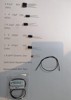
Then I
removed the two rubber feet still attached to the bottom of the Spectrum; I don’t
know why two rubber feet were missing from this computer when I bought it but a
replacement pack set me back about £7 from Mutant Caterpillar (I thought that
this was a wee bit pricey to be honest but as they are not in general
production any more, I can understand why they were the price that they were)
As I was
going to wash the case of the Spectrum I had to strip absolutely everything out
of the computer starting with the cassette drive unit which also had my TZX
Duino Amplifier fitted alongside of it.
I started by removing the
TZX Duino amplifier
Then I
removed the five smaller cassette drive screws
There is a
longer self tapping screw which needs to be removed and that is located here
After
that I removed the power LED PCB from the case, this is only held on by one self
tapping screw and it can be found by flipping the drive unit over as seen in
the picture below.
The
only other thing preventing the drive unit from being lifted out was my TZX
Duino amplifier input jack socket. To remove that I needed to use some fine
pointed pliers to get a grip on the locking nut.
Next up was
the removal of the keyboard from the case; this is done by removing the four
highlighted screws shown below.
It
was whilst I was removing these screws that I noticed that one screw wasn’t coming
out. This indicated to me that there must be some damage to the screw hole boss
on the case of the +2. So I carefully lifted the keyboard out.
And found
that indeed the screw hole boss was broken. The easiest way to remove the
broken boss is to simply hold the boss with a pair of grippy pliers and use a
screwdriver to unscrew the screw.
I put the
broken boss in a safe place and would repait it later.
The next
thing to do was to remove the metal backing plate from the keyboard and this
can be done by removing the four highlighted screws shown below.
Then carefully
unclip the backing plate away by gently pushing on the black clips and prising
the plate away at the same time.
The
next thing to remove was the keyboard membrane; although the membranes of the
+2 are far superior to that of the ZX Spectrum 48k’s, care should be taken when
removing them as they can easily be torn. The membranes themselves are made up
of two layers and it is a good idea not to separate them (unless they need
cleaning individually)
The
membrane on this Spectrum +2 is in surprisingly good condition; almost like new
in fact so there was no need to clean it at all.
I then
dusted the plastic keyboard housing with a soft paint brush then started to
remove the keys.
This is
done by using a small screwdriver to gently lever the plastic locking clip away
whilst pulling the key away from the other side. Again care should be taken
when doing this as sometimes the plastic in the keys become brittle and are
easily broken.
When
removing the keys it is a good idea to separate the keys from the springs so I
used two old ice cream containers for this purpose.
When you
come to the larger keys you will find that they have a metal supporting bar
fitted; the easiest way to remove these is to lever the ends out first (from
the grey plunger part of the key) then gently pull the bar away from the tiny
black plastic clips on the housing of the keyboard.
The Enter
key is the only key with a different spring and has a smaller diameter so that
is something to keep in mind when you come to replacing the keys after the
cleaning.
Removal of
the keys is just a repeat of the process described above.
Once all
the keys have been removed, it is time to give them a clean; I am fortunate
enough to have an Ultrasonic Cleaner so opted to use that but cleaning the keys
can easily be done by using soapy water and a toothbrush.
I used ultrasonic
cleaning solution for this purpose but could have simply used water. My
ultrasonic cleaner also has a heater but it is a good idea not to use this for
cleaning plastics as the ultrasonic cleaning process will also heat up the
solution as it cleans. If you add more heat to the process then you can easily
overheat the keys which could result in warping the keys.
I set the
cleaner to five minutes and prepared my workbench with paper towels for the
drying process.
It
is a good idea to dry the surface of the keys with a paper towel after cleaning
as sometimes you can be left with watermarks on the keys if allowed to simply
dry naturally.
Then
sit the keys on some paper towel and allow to dry naturally.
Next up
were the springs; I cleaned them in exactly the same way; five minutes at room
temperature without the heater being switched on the ultrasonic cleaner.
Then sit
the springs on some paper towel and allow to dry naturally.
With the
keyboard drying, I then turned my attention to the case of the +2. Firstly I
removed the cassette lid from the top of the +2. This is done by removing the
screw and spring shown below.
Then gently
lever the hinge clips on the underside of the case until the cassette lid is
free to simply slide out.
And here we
have a completely stripped top part of the ZX Spectrum +2
With
everything stripped down it was time to clean the +2. I did this using soapy
water and a toothbrush. When cleaning the top of the +2 I was careful not to
brush too hard on the painted parts (the red Sinclair and 128K as well as the silver
ZX Spectrum +2) as the paint can easily be worn away by excessive brushing.
I started
with the keyboard housing as shown below.
And I used
a cotton bud to clean out the key holes on the housing.
After that I
cleaned the cassette lid.
Then the
top of the +2
And finally
the bottom half of the +2
As with the
keys, it is a good idea to rinse then dry the plastic with a paper towel to
reduce the chance of any watermarks on the case.
Then set
aside and allow the plastic to dry out completely.
After it
had dried, I turned my attention to the broken screw hole boss. I used superglue
to stick the boss back on to the case of the +2 but in my experience this is
never strong enough to fix the boss on permanently so I used epoxy resin to strengthen
the boss as the base. As shown in the pictures below.
Set the
case aside and allow the epoxy resin to cure; I used quick setting epoxy for
this purpose which claimed to cure completely in around 20 minutes. However as
there was a thick (ish) layer of epoxy at the base of the boss, I knew that
this would take a little longer to cure.
As the keys
and springs had dried out completely I turned my attention to refitting the
keyboard. When refitting a keyboard, I like to lay out the keys in the order of
the actual keyboard as shown below.
Remember to
fit the springs to the keys before fitting them in place.
After
fitting the springs the keys simply click into placeby gently pushing down on the key until you
hear a satisfying click.
One thing
to remember is that the Enter key has the smaller diameter spring so ensure you
fit the smaller spring to that key.
After
fitting all the keys, you should have something looking like this
Now to fit
the support bars to the larger keys.
Turn the
keyboard housing upside down then fit the bars.
I started
with the space bar as this looked like the only different supporting bar.
Fitting it
is relatively simple; I slid the ends of the bars into the slots on the grey
plastic plunger part then used a pair of tweezers to slide the middle of the
bar into the black plastic clips on the keyboard housing. Again, care should be
taken when doing this as the black plastic clips are rather small and pretty
fragile.
I had a
whole lot of trouble fitting the Extend Mode supporting bar (shown below)
Until
I finally realised that the supporting bar for that key was slightly deeper in
width... It only took me about five minutes LOL
Correct supporting
bar fitted now!
Once done
you should have something looking like this
Now refit
the keyboard membrane; again, try not to separate the two layers of the
membrane when doing so.
Then refit
the metal backing plate; this simply pushes on with a satisfying click sound
when doing so. Ensure that all black clips have been seated correctly and that
the backing plate is sitting flat.
Then refit
the four small fixing screws on the holes beside the membrane tails as shown
below.
After that
I refitted the cassette lid to the top panel of the +2. Slip the hinge part
through to the underside of the +2 then gently lever the hinge pins into
position.
Then refit
the spring; the picture below shows the correct orientation of the spring.
Secure
the spring with the fixing screw then refit the keyboard.
Care should
be taken to fit the screws in the correct position as failure to do so will
result in you not being able to fit the main case screws to the +2. A reminder
of the positions of the crews is shown below.
Now we can
refit the cassette drive and TZX Duino Amplifier.
Start off
by refitting the TZX Duino Amplifier input socket. This is done by using a pair
of fine nosed pliers and carefully tightening the nut with them (you can buy a
proper tool for this purpose but I do not have one in my toolkit)
Then refit
the power LED PCB in the position shown below.
Next refit
the TZX Duino Amplifier by simply pushing the PCB’s fixing holes on to the PCB
stand off’s
Then refit
the actual tape drive; below is a picture of the locations of the 5 smaller
screws.
The longer
self tapping screw gets fitted in the position below
Once fitted
I turned my attention to the bottom half of the +2; I started by sticking the
serial number back on. As the serial number had lost its ‘stick’ I decided to
use double sided sticky tape. I used my thinner tape for this and it was almost
a perfect fit.
Trim away
the excess tape with a scalpel
Then fit
the serial number back on to the bottom of the +2 as shown below
Then fit
the new rubber feet by pushing them firmly into the holes on the bottom half of
the +2.
After that,
refit the main circuit board to the bottom half using the 6 smallest self
tapping screws
Having done
that, I decided to replace the old 1.5 A rated 7805 with a new 2A rated version
(L78S05CV) Although I have never had a 7805 fail in the past I thought that as
I had a new one in stock at home that it wouldn’t do any harm.
My camera didn’t
pick up a whole lot of this part of the modification as I had it out of
position but it is pretty straight forward. The pin out on the new L78S05 are
exactly the same as the old 7805 so swapping the wires over is easy; just make
sure that you solder the wires in exactly the same position.
I am unsure
whether all +2’s have the same colours of wires but in my case the input wire
was brown, GND was Black and the Output was Red. Below is a picture of my wiring
diagram for the 7805
Firstly
remove the old 7805; I found that the screw was pretty tight so be sure to use
an appropriate sized screwdriver to remove the screw otherwise you will risk chewing
up the head of the screw.
Then clean
the old heatsink compound from the heatsink with some IPA
Prepare the
new L78S05CV for soldering by trimming the legs slightly and tinning each leg
at their ends.
Then slide
the old insulation sleeving from each leg of the old 7805 then transfer and
solder the wires one at a time on to the new L78S05. I had planned to use some
new heatshrink for this job but the old sleeving was in very good condition so
I opted to use the original sleeving instead.
After that,
apply some heatsink compound to the new L78S05.
Then fix
the new 7805 to the heatsink as shown below
All we have
to do now is to reassemble the +2 and test.
Fit the voltage
regulator connector
Then fit
the keyboard membrane to the PCB
After that
fit the cassette drive connector to the PCB, fit the lid and screw in the six
case fixing screws.
As a wee
treat I bought new screws for this purpose; I wanted the +2 to be as authentic
as possible so bought new black screws for the job. I found that 12mm M3 Self
Tapping screws were the correct size and length and managed to source 100 of
them from Aliexpress for about £1.92 plus shipping.
Now all I
had to do was test the system. Below are some pictures of the finished +2,
plugged in and working!
I am
absolutely thrilled with the finished product here; it is picture perfect and
sparkly clean. I have had a blast working on this project and am a little sad
that it is now over. Here’s hoping that this +2 will continue to work for at
least another 35 years!
A youtube
clip of the complete process can be found below.
Thank you
again for taking the time to read this very long entry. If you have any
questions or queries about this mod or any of my others please feel free to
leave a comment or email me directly at


Comments
Post a Comment