Repair and restoration of retro consoles, 8 bit computers. In this blog I hope to show you how to repair, retrore and modify old consoles and handhelds, from manufacturers such as Atari Amstrad Acorn Sinclair Commodore Dragon Sony MSX BBC Playstation Sega Microsoft xbox Spectrum ZX81 Vic 20 VIC20 C64 Amiga Binatone Grandstand.
Apologies for the delay with this entry; varied reasons include school holidays, two birthdays and some minor repairs of some retro console birthday gifts! Please feel free to use my PCB and 3D printed housing designs found on my Github and Thingiverse should you wish to make your own joystick adapter. Here is the TI994a working with the FlashRom99 and my Joystick Adapter circuit. Here are all the components required for this mod. The gerber files for my PCB design can be found on my Github. https://github.com/Alleged-Geek/TI99-4a-Joystick-Adapter/ And you are looking for the zip file named below if you are going to send the gerber file off to be manufactured. ti99-4a-adapter_2022-07-27.zip My github also contains stl files for printing the housing. And here is my version of the schematic diagram. You will need 10 X IN4148 signal diodes which can be found on eBay. 1 X DB9 D-SUB 9 Pin Female connector, again found on eBay. 2 X DB9 D-SUB 9 Pin Male connector al...
Get link
Facebook
X
Pinterest
Email
Other Apps
Commodore VIC 20 - Restoration; Part 2, Video Modification, Electrolysis Rust Removal and Electroplating!
For this
entry, I am revisiting my VIC 20; I was very happy with the work I did but the
Video Out Signal to my LCD TV was pretty rubbish as can be seen from the
following photo.
I decided
to have a look and see if there was something I could do about it and stumbled
across the following Youtube clip
Here, Noel
talks about faulty VIC chips and the fact that he stumbled across his modification
by accident! Glad he did as the results are pretty spectacular. Many thanks
Noel!
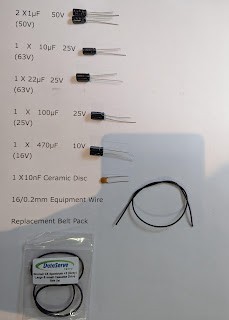
Here is a
list of the components and tooling required for this modification.
220pF
Ceramic Disc Capacitor
100nF
Ceramic Disc Capacitor
470pF
Ceramic Disc Capacitor
Thin piece
of equipment wire (I used yellow 10/0.1mm equipment wire)
A small
piece of heat shrink sleeving (I used 1.5mm sleeving)
Heatgun
(for sleeving; you can use a soldering iron to do this part but will need to be
careful)
Soldering
Iron
De
Soldering Pump (solder sucker)
Pliers
Cutters
Wire Strippers
Tweesers
(optional)
Flux (again
optional)
Isopropyl Alcohol (again optional)
The 220pF
Capacitor has the following markings
221
The 100nF
Capacitor has the following markings
104
The 470pF
Capacitor has the following markings
471
Now let’s have a look at
the schematic.
Here is a
close up of the circuitry we are interested in.
The mod on
Youtube advises that we remove FB7 and replace it with a 100nF Ceramic Disc
Capacitor.
It then
advises that we replace C13 to its original position (I will add photos later)
And finally
it advises that we solder a 470pF Capacitor from pin 2 of the VIC Chip to the
video output connector.
Highlighted
below is FB7 and C13 on the schematic
Here is a
picture of the modified schematic.
Highlighted
is the area on the mainboard that we are interested in.
And here is
a close up
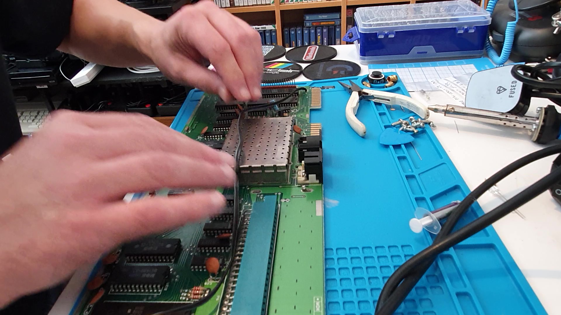
Look at the
state of that RF Shield! Age it appears has not been kind to it! As I have
invested a wee bit of time into restoring this beautiful computer, I decided
that I should do something about the RF Shield. All will be revealed once I
have completed the video modification!
Firstly,
and I advise you do this; remove the RF Shield completely as this will give you
easier access to the components you are going to have to change and move
around.
This is a
wee bit trickier than it looks and may give problems to those without
adjustable soldering irons. I tried my electric de-soldering pump to try and de-solder
the joints on the circuit board which hold the RF Shield in place.
Unfortunately, my electric de-soldering pump couldn’t supply enough heat to
melt the solder on the vias. So it was back to my trusty twenty year old RS
Solder Sucker and soldering iron.
I turned the
temperature up on my soldering iron, heated the solder joints and removed as
much of the old solder as I could. Unfortunately, this did not remove enough
solder in order to simply lift the RF Shield off the circuit board.
Now, I had
a couple of options here; one safe and the other not so safe.
The first
option I considered was to heat the pins up individually then prise the rf
Shield up on each corner… not safe! This could damage the Vias on the circuit
board.
So I opted
for the safer option which was to resolder each joint with fresh solder, then try
the whole de-soldering process again. This worked slightly better but it did
take a couple of goes on a few of the solder joints.
The RF
Shield was still a bit tight but I found
that if you get a small flat headed screwdriver and gently prise the shield up
on each corner (ensure that all solder is removed beforehand) it will lift up
and you should have a circuit looking like this.
The two
components we need to remove (C13 and FB7) are highlighted below
As I did
earlier to remove the shield; I re-soldered each joint then de-soldered. I will
add pictures of this process below
Apologies
for the clarity of the next couple of pictures showing the removed components
(they were taken from a video clip)
The above
photo shows the removed Ferrite Bead FB7
The next
component to remove is C13 (it is a 220pF Capacitor which looks like a resistor
and has been placed diagonally and soldered) It looks like this is a standard
factory modification made by Commodore as there is actually a space for C13 on
the circuit board with one of the via’s going to a different part of the
circuit.
Refitting
that 0.4inch pitch into a 0.1 inch pitch would be extremely difficult so I opted
to use a new regular 220pF Ceramic disc capacitor.
Below is a
photo of the PCB with C13 removed.
Now it was
time to solder the new components into the circuit. Before I did so, I added
flux on the Vias and solder points for the additional 470pF capacitor. I used a
cheap and cheerful flux pen for this. Care should be taken using this type of flux
pen as if you push down too hard on the tip the flux gushes out the pen!
Now it is
time to solder in the components; I started with the 220pF Ceramic Disc
Capacitor (221) This goes where C13 should have originally been before
Commodore modified the circuit at the factory. The silkscreen on the mainboard
shows you exactly where to place it.
Below is a
picture of where it goes (taken after the modification)
As you can
see from the photo, the capacitor is sitting flat against the circuit board; this
is good electronics practice. To ensure that the component doesn’t slip down
when you turn the PCB for soldering you can gently bend the legs of the
component to about 45 degrees whilst holding the capacitor flat on the
component side. (see photo below)
Next up is
the 100nF Ceramic Disc Capacitor (104); this goes where FB7 was positioned.
Again
ensure that the component is sitting as flat as possible on the circuit board
then solder.
Now we come
to the trickiest part of this modification; soldering the 470pF Capacitor (471)
in place. As this is a new component there are no Vias to stick the legs
through; care should be taken to solder the component legs on to the correct
place.
One leg of
the Capacitor is soldered on to Pin 2 of the Vic Chip; I actually didn’t solder
directly on to the Vic Chip as I didn’t want to risk overheating the pin on the
chip so I soldered it on to the correct Via of C13 (the 220pF capacitor we
soldered earlier)
Below is a
photo of the finished mod taken after the capacitor was soldered into place.
As you can
see from the photo, I have used heatshrink sleeving to insulate the other leg
of the capacitor (the one which has a wire soldered on to it) This is just in
case the bare wire/leg of the capacitor short circuits against another part of
the PCB when the PCB is secured down to the bottom of the Vic 20 Case.
I cut the
leg of the capacitor going to be soldered on to C13 quite short as it would be
difficult to use heatshrink sleeving on the component leg.
I then
tinned the end of the cut leg (applying solder to the leg by heating it up and
melting solder on to it)
Next up is
to solder it on to the correct Via.
Tin the
other leg of the capacitor as close to the capacitor as possible then trim the
excess leg away; this will reduce the length of heatshrink sleeving you will
require to insulate your solder joint for the wire which will go to the output
video connector.
Now prepare
your piece of wire; I used 10/0.1mm yellow equipment wire as it is nice and flexible
(the thicker the wire the less easy it is to solder and route around the
circuit board) Thicker equipment wire is also a wee bit more expensive as well
(you know how us Aberdonians are; we actually invented copper wire when two Aberdonians fought over a penny they found lying on the pavement… true story ;) )
Strip about
5mm of the insulation off one end of the wire; twist together tightly and tin
the end. This will prevent fraying of the wire when you actually solder it on
to the capacitor leg and it also makes it easier to solder.
Now solder
the wire on to the capacitor leg; I would recommend you use a Butt Solder joint
for this as if you wrap the wire around the leg the solder joint will be wider
than it should and you may not be able to use the 1.5mm heatshrink sleeving as
it would be too small to slide over the solder joint.
A Butt
joint is where you solder the wire on to the leg in a straight line; basically
line them up in parallel, heat the component leg with the soldering iron and
then lay the tinned wire on to the component leg, wait until the solder melts
on both the capacitor leg and tinned wire then remove the soldering iron (try
not to move the wire or capacitor whilst the solder cools down as this will
result in a poor solder joint)
Cut enough
Heatshrink sleeving to completely cover the solder joint slide it over the wire
all the way to the capacitor then use either a heatgun (as I did) or your
soldering iron to shrink the sleeving. Care should be taken doing this as it is
easy to melt the wire or in some cases damage the circuit board.
Finally for
this mod, we need to solder the other end of the wire to Pins 4/5 of the Video
Output Connector. This is pretty straightforward; strip about 5mm insulation
off the end of the wire, twist the wires together then tin.
Use
tweesers to hold position the wire at the correct place on the circuit board,
heat and melt the solder on the Via then slide the tinned wire on to the via
creating a good connection. Try and ensure that the wire is lying flat on the
circuit board as you do not want it sticking up at an angle.
Hopefully the
470pF Capacitor will look like this.
Now it is
time to clean up the soldering with Isopropyl Alcohol. I will be expecting
another complaint about a funny tasting toothbrush tonight from Mrs Geek ;)
Now all
that has to be done for this part of the restoration is test that video output.
As I am
planning to further work on the VIC 20, I didn’t completely screw the whole computer
together.
Now it was
time to test; I used my VIC 20 Data Cassette Recorder to load Trap as I wanted
to test everything with the VIC 20 after working on the Mainboard.
Here are
the results
Original
Video Output
Modified
Video Output
As you can
hopefully see, there is a vast improvement in picture quality. The original
picture had jail bars and some of the text was a wee bit hazy (especially on
the red ‘High Score’ lettering. The modified picture is so much sharper and has
no real visible jail bars. I am absolutely delighted with this modification.
Many thanks
and much respect go out to Noel’s Retro Lab for posting this modification on
Youtube!
On a wee
side note; should I wish to return the VIC 20 to its original state, I have
bagged and stored away the original components. This should be a relatively simple
job as there were no destructive modifications made to the mainboard.
Now for
Part two of this entry!
I am
actually quite excited about this part as I have never done it before. I
absolutely love learning new techniques and processes so when I noticed the
corrosion on the RF Shield I thought that I could do something about it.
I could
have bought some rust eating gel but that would have been no fun… Instead I
turned my attention to Electrolysis Rust removal. Finally I have found a use
for something I was shown in Chemistry at school more years ago than I care to
remember ;0) I am sure that my old Chemistry teacher would approve!
Let’s have
a look at that corroded RF Shield again
Ugghh! Looks
completely out of place in my sparkly clean housing!
Time to do
something about it!
The
parts/ingredients needed for the electrolysis rust removal are as follows
Baking Soda
or Salt
Water
Plastic Tub
Something
to secure the Iron anode
An Iron
Anode (I used an old screwdriver)
Car Battery
Cables with
croc clips (to fit the battery and attach to the Anode and rusted part)
Wire Wool
(I used a soap filled pad)
Polishing
compound (Optional)
You may want to use gloves as well as it is quite a dirty process.
Below is
the wiring Diagram
And here is
a picture of my prototype setup
I filled
the old DVD box lid with water about 80% full then put two teaspoons of
Bicarbonate of Soda then stirred until completely dissolved. Rather crudely, I
placed the screwdriver in the tub and secured it to the side with insulating
tape (which wasn’t my best idea ever ;o) ) I connected the positive cable to
the screwdriver and the negative cable to the lid of the RF Shield then plugged
in the cables to my car battery.
I switched
on and hoped for the best!
Almost
instantly I saw the reaction I was looking for
The
solution started fizzing and there was a whole lot of action going on at the
Anode… It was working!
This is a
picture after an hour
And after a
couple of hours it looked like this.
As a wee
side note: it is worth rotating the part 180 degrees periodically as the rust
is attracted to the anode better with line of sight.
Looks
pretty disgusting doesn’t it?
Time to
give it a clean.
Unplug the power first then remove the part.
Not bad at
all!
It still
looked a bit tarnished but I thought that a scrub with some wire wool would
take it up nicely. I also used some polishing compound (see picture)
And here is
the result
Looks fantastic!
Now time to
build a better electrolysis station.
I used a
larger plastic container and stuck an adhesive cable tie base near the top then
I secured the Anode (screwdriver) in place with a wire strip (the kind you get
on new cables)
Here is a
picture of the Electrolysis station MK2
I then
repeated the process used for the lid of the RF Shield on both the housing for
the RF Shield and the metal housing around the edge connector.
And after
much scrubbing, this is what I am left with!
Three
sparkly clean parts! Beautiful!
But I don’t
want to leave things there as after another 40 years, the RF Shield will look
exactly the same as it did, so I decided to try my hand at another new process…
Electroplating!
I have
never done this before either and was very surprised at how easy it looked.
I have had
an agonising wait for parts ordered on ebay but they finally arrived today…
time to get to work!
What you
will need is
Vinegar
Nickel Anodes,
either plates, rods or the very thin anode strips
Salt
Car Battery (or another power soure)
Connectors
Gloves
Some kind of filter if you
use the thin anode strips as they break up whilst making the Nickel plating
solution.
A 3.5 – 5V
DC Power Source (I built a crude 5V Regulator with a Diode on the output to
give me a little volts drop from the 5V)
Now a wee
word of warning… This is a smelly process! Your house will stink of vinegar if
you do this indoors.
And on
another note; I must apologise to Aberdeen and the whole north east of Scotland
for the eruption at Mount Geek at around 7am on Friday Morning. Mrs Geek woke
up and exploded! The house was reeking! Some of the things she called me were
quite unflattering and I even had to look up some words! I got the feeling that
she wasn’t best pleased ;o)
Ohhh,
almost forgot, and this is very, VERY important; you should NEVER EVER under
any circumstances ask how to spell such words when you try and google them
later on… for some reason and I don't know why, this made matters worse... a whole lot worse!
Anyhoo,
back to the Electroplating!
Let’s set
up the container
Firstly,
pour in the Vinegar (I used three 575ml bottles)
Next, add
the salt (I guess that I used about three tablespoons worth)
Then stir
until the salt is completely dissolved.
Now we come
to wiring up the Nickel Acetate production circuit.
I started
with the Single strip attached to the negative connector on one side of the
container and the 4 or 5 strips connected to the positive connector on the
other side of the container. Unfortunately, the distance between the two was
too great for a good reaction so I moved them closer together.
I then powered
up the circuit; it is worth noting that as I was using quite a volume of
vinegar/salt solution, this was going to take some time (four hours in fact)
Changes are slow but after around ninety minutes you should have a very faint
green tinge to the solution. Also around the ninety minute mark, I found that
the 4 strips of nickel on the Positive connector had been completely dissolved
into the solution.
Great it was working!
Below is a
picture of the dissolved Nickel Strips
I replaced
them with another four strips and reconnected the negative wire
I had to
replace the Nickel three times in total over the four hours it took to get the Nickel
Acetate to what I thought was the correct darkness of ‘green’
Below is a
photo of the dissolved Nickel Strips
And below
is a picture of the Nickel Acetate after four hours of cooking
As the
Nickel breaks down and dissolves in the container you are left with what can be
best described as Nickel powder and Nickel Granules lying at the bottom of the
container. Obviously that will have an effect if left in the container when we
use the Electroplating process.
From what I
had read about it, it can lie on the part you are plating and will then be
plated over leaving you with a rough finish.
Time to
filter out those Nickel particles.
Place your
filter on top of your new container as seen below
Then
carefully pour the Nickel Acetate into the new container.
And
hopefully you will catch most of the impurities. I think that I will use a
paper filter next time as the solution was still a wee bit cloudy for my
liking.
Below is a
picture of what I managed to collect in my 3D Printer filter.
Next,
refill up your old container as we are just about to start the Electroplating
process
From what I
have read about electroplating with Nickel, it requires a voltage range between
3.5 – 5V DC. As I have a 12 V car battery as my power source I would have to do
something about that. I decided to use a L7805 1.5A Voltage Regulator as my
main drop down then decided to put a 1N4004 diode in series with the output to
drop it down 0.7V (just to be on the safe side)
Below is a
picture of my schematic
As I couldn’t
wait to make a PCB, I decided to knock one up very quickly. It is a bit Heath
Robinson but it did the trick. I was getting a steady 4.5V DC at the output
Below is a
picture of my Voltage Regulator Circuit
Now it was
time to set it all up; refill the original container with the Nickel Acetate,
then connect the positive wire to a single Nickel Strip as seen below.
I am not an
expert in this but I did read that it is best to try and keep the part being
plated moving as the bubbles formed as part of the process can affect the finish
so I spent a fair bit of time standing over the horrible vinegary smelling
solution either moving the wire to knock the bubbles off or turning the part
around so that everything gets plated evenly. The Youtube clip at the end of
this entry shows this better than I can describe.
After about
an hour in total, I washed each part and dried them. Below is a picture of the
result
They weren’t
quite what I expected (I was hoping for super shiny) but this was my first time
doing this. I have since read that you can buy additives which will give a
different finish on the plating.
Having said
that, I am delighted with the finish, they look ok and I know that they will
not rust the same way they did before (hopefully
good for another 40 years!)
Now it is
time to refit the parts.
Starting
with the housing for the RF Shield around the VIC chip.
Solder the highlighted
Via’s. I recommend you turn the heat up on your soldering iron as it takes a
fair bit of heat to get the temperature warm enough to flow solder on the
shield pins.
Take care
not to melt the wire from the 470pF Capacitor
Next, fit
the lid; it simply pushes on
Now, refit
the edge connector cover
Turn the
board upside down and grab the locking clip with a pair of pliers
Gently
twist each locking clip with the pliers to lock the cover in place
And here we
have it, a fully restored PCB
Now fit
everything together, below is a picture of the bottom of the VIC 20; remember
to fit the black bezel for the power, switch and joystick port before screwing
it together. Then refit the keyboard and LED connector and finally screw in the
final three fixing screws
Time to re-test
the system, again I decided to load a tape game (just to check full functionality)
Wire it up as shown and switch on
Load the
game
and...
and...
Success!
Another
restored computer.
This VIC 20
has been a real pleasure to work on; it is a lovely machine! Well built and
easy to work on and believe it or not the PCB was in much better condition than
its younger brother (my C64) I absolutely loved this project!
On a
personal note, I love learning new techniques; the whole electrolysis and
electroplating was completely new to me (apart from when I was being bored
stupid during my chemistry lessons at school) but that was about 35 years ago
and I am sure that my old chemistry teacher would approve ;o)
During this
project I have learned
VIC 20
Video Modification (thanks to Noel’s Retro Labs)
Electrolysis
Rust Removal
Electroplating
And as an
added bonus; I even learned new curse words (thank you Mrs Geek)
However, I
did learn that you should never ask how to spell such curse words!
Thank you
for taking the time to read all the way though this entry (it was rather long)
If you have
any questions or queries, please feel free to get in touch either through the
blog or email me directly at


Comments
Post a Comment