Repair and restoration of retro consoles, 8 bit computers. In this blog I hope to show you how to repair, retrore and modify old consoles and handhelds, from manufacturers such as Atari Amstrad Acorn Sinclair Commodore Dragon Sony MSX BBC Playstation Sega Microsoft xbox Spectrum ZX81 Vic 20 VIC20 C64 Amiga Binatone Grandstand.
Apologies for the delay with this entry; varied reasons include school holidays, two birthdays and some minor repairs of some retro console birthday gifts! Please feel free to use my PCB and 3D printed housing designs found on my Github and Thingiverse should you wish to make your own joystick adapter. Here is the TI994a working with the FlashRom99 and my Joystick Adapter circuit. Here are all the components required for this mod. The gerber files for my PCB design can be found on my Github. https://github.com/Alleged-Geek/TI99-4a-Joystick-Adapter/ And you are looking for the zip file named below if you are going to send the gerber file off to be manufactured. ti99-4a-adapter_2022-07-27.zip My github also contains stl files for printing the housing. And here is my version of the schematic diagram. You will need 10 X IN4148 signal diodes which can be found on eBay. 1 X DB9 D-SUB 9 Pin Female connector, again found on eBay. 2 X DB9 D-SUB 9 Pin Male connector al...
Issue 2
Acorn Electron, restoration, retrobrite, repair and building my own version of
a TZX Duino
This entry
came about when my 8 year old (who is now known as apprentice-geek) asked if he
could solder one of my TZX Duino PCB’s.
Inspired by
the ZX81 board that I designed and populated, he asked if he could do one. It
was a no brainer for me; he is showing great potential and has worked on two
previous boards. First one was a comparator circuit which I use at work for
soldering practice with students, he did a fantastic job so next up was to
actually design a circuit board… so together we designed a noise-o-meter ;0) didn’t
quite work as planned though as instead of making him quieter, he decided that
it is great fun to get the LED’s glowing as brightly as he could!
When he
asked if he could solder one of the circuit boards, I asked him which system
would he like to make it for and offered the Dragon 32 (which was an amazing
project for me) but he being a Nintendo person was a little concerned about
Donkey King and the fact that it was definitely an unlicensed Donkey Kong clone
so instead he opted for the Acorn Electron. Good choice apprentice-geek!
I did this
restoration before I started this blog so only have a few photos of the
process, but most of the information needed is there, I hope that you find my
entry useful and interesting.
Acorn
Electron Strip Down
This system was an ebay find, quite a good price and came
with original software titles and more importantly a working power supply (they
can be quite expensive to replace) It did have a couple of issues; an
intermittent keyboard and a wee problem with the display but I will go into
that later.
First things first, let’s have a look inside this beautiful
machine
Remove the four highlighted screws with a medium sized
crosshead screwdriver and place them somewhere safe (the Electron has screws of
varying length so try and sort the screws in some kind of order)
Care should be taken when removing the top; the keyboard
ribbon although looks quite sturdy can be easily torn so lift the lid from the
back to the front to avoid any damage.
Isn’t that a beautiful sight, plenty of space to work with,
everything easily removable… fantastic piece of electronic engineering!
The keyboard ribbon (highlighted) should be removed at this point; my only
advice he is not to pull on the actual ribbon cable itself. Instead grip the
ends of the connector and ‘wiggle it out’ (technical term ;0))
Now we have the Electron in two parts. I have to admit to
being quite pleased with the condition of this wee Elk, everything was
clean-ish inside, no real dust or grime inside it which is remarkable
considering it’s age. Here is a close up of the main board
Time to start removing the circuit boards. There are four
other connectors to remove; the loudspeaker, two a.c. connectors and a d.c.
conector. First up the loudspeaker; note that the white wire is to the left although
it will work if you reconnect it incorrectly. Pull up on the connector to
remove it from the header pins and the loudspeaker will simply lift out.
After that, remove the a.c. connectors; again it does not really matter which way round these are connected. Simply pull up on the connectors to remove them.
Next remove the d.c. supply; this is a 3 pin connector (note
that the red wire is closest to the bottom of the housing) It slides out to the
right and I advise that you use the actual plastic connector to wiggle it out
as pulling the wires could result in broken wires.
Now remove the four main board fixing screws (highlighted)
with a medium sized cross head screwdriver.
Now remove the four main board fixing screws (highlighted)
with a medium sized cross head screwdriver.
Once the mainboard has been removed, clean the dust away with
a soft bristled paintbrush, use a toothbrush and isopropyl alcohol to clean the
solder side, checking for any suspect solder joints afterwards. Then clean the
component side with cotton buds and isopropyl alcohol. After cleaning, check
the condition of the electrolytic capacitors for any leaks or bulging and
replace as necessary.
Once that is done, remove the three fixing screws on the
power supply PCB (highlighted) then repeat the cleaning and inspection process.
Now let’s have a look at that keyboard. Unscrew the five
crosshead screws from the lid (highlighted); the keyboard should simply lift
out after that.
Remove the individual keys; there are several ways to do
this, either pull them off the keyboard with your fingers or you can carefully
lever them off with a flat headed screwdriver. Alternatively, you can buy a
specialised key removal tool and use that to remove them.
The spacebar is a little bit tricky as there is a metal clip
which is a wee bit fiddly to remove; pull the spacebar up, then slide to one
side, unclip the metal clip from one side then remove the key.
Let’s have a closer look at that keyboard
As
you can see there is some flux residue on the highlighted solder joints; this
particular keyboard was working intermittently with several keys. I cleaned the
whole PCB using Mrs Geek's toothbrush and isopropyl alcohol, and then inspected
the solder joints. They were still looking suspicious so I de-soldered, cleaned
then re-soldered each joint in question. Below is a photo of the cleaned and
re-soldered PCB.
We should now have all the parts disassembled for the
retrobrite process; now it is time to clean them all. The process is exactly
the same as the one shown in more detail in my last entry (Vic 20 (the 3 R’s)
Basically, scrub each part with a toothbrush and washing liquid, rinse thoroughly
then dry everything before the application of the 40% Cream Peroxide.
Lay clingfilm on a flat surface; overlap several strips
until the clingfilm is about 60% wider on each edge of the part being
retrobtited. Wear
appropriate PPE (safety glasses ad gloves) then apply the cream peroxide with a
paintbrush; try and get an even
coat and care should be taken not to cover any labels on the part being
retrobrited as this could result in blistering. I lucked out during this
retrobriting (it was my first attempt at it) and thankfully didn’t damage the
Acorn Electron label on the top panel.
As I mentioned earlier, this was my first attempt at
retrobriting; I had trouble when rotating/moving the keyboard components during
the ‘baking’ process. A way round this problem is to lay the keyboard out on a
flat surface (I use a glass chopping board) and that can be easily moved
without disturbing the keys.
Now time to bake the parts in the sun; rotate each part 90
degrees every hour as well as massaging the cream peroxide on each surface.
This will ensure that each side of each part gets an equal amount of sun as
well as preventing the cream peroxide from dying out which could leave a
streaky finish.
After four to six hours in the sun take the parts in and wash and dry thoroughly. You dont want any cream peroxide left on any part of the case or keys. Pay particulat attention to screw holes and little noks and crannies.
after washing and drying with paper towel, I like to place the parts in the sun to evaporate what little water is left on the parts; this is especially important for the keys ans screw holes so lay them upside down and let the sun do its work.
Now it is time to reassemble the computer.
Starting with the keyboard, below is a photograph of the newly retrobrited keys
Before refitting the keys, give the aluminium base of the
keyboard a clean; I find a soft paintbrush followed by a clean with isopropyl
alcohol and cotton buds the best method for this process.
Refit the keys in their correct positions; the space bar is
fiddly but if you reassemble it exactly in reverse to the way you dis-assembled
it, you shouldn’t have too many problems.
Now lets refit the keyboard to the lid of the computer; simply screw the five cross head screws into their original position. And here we have a squeaky clean top part!
Lets rebuild the bottom half of the Electron
Refit the Power suppy with the three power supply crosshead screws
Then refit the mainboard with the four mainboard crosshead screws
Re-attach the power supply connectors; the grey a.c. wires simply push on to the two pins to the top right of the mainboard (it does not really matter which way round these go) the two wires will then fit into the groove on the plastic so that they do not become trapped and crushed when the Electron is screwed together.
After that, slide the three pin d.c. connector on to the pins to the bottom right of the mainboard (note that the red wire should face towards the bottom of the Electron.
Now, fit and reconnect the loudspeaker. It easily slips into
the slot on the top left of the case then attach the connector to the top left
of the mainboard (note that the white wire should be on the left side)
Now refit the keyboard to the mainboard using the single in
line socket (note this can be quite fiddly especially if the pins on the
pinheader have bent out of shape during the removal of the connector) Also
worth noting is the fact that the socket has some exposed connections facing
down towards the mainboard which has to be insulated. There should be a sticky
foam insulator which will stick on to the connector; if not simply use some
insulating tape as shown below (I removed that afterwards and used the foam
insulator)
Finally, screw the Electron together using the four
crosshead fixing screws.
And here we have a restored Acorn Electron… looking
beautiful!
Now lets turn our attention to the cassette input to the
Electron; I do have some original tapes for this computer but age it appears to
have caught up with them and they do not load reliably so after a bit of
research; I found out that you can use a TZX Duino and load a version of the
software which supports the Electron UEF format rom files. I did buy a TZX
Duino kit from ebay and although it was a very good price and works flawlessly but
I didn’t like the fact that components were on both the solder side and
component side, so I designed my own version.
I laid out all the components on the component side, manufactured a prototype then sent my design away to JLPCB for manufacture. I got five double sided, plated through hole, solder masked ans silk screen printed PCB's delivered in around two weeks for under £10! Fantastic value!
You can download my design from my new Github site on
https://github.com/Alleged-Geek/TZX-Duino
There you will find a zip file which contains all the files
that JLPCB need to manufacture the PCB; I have also included the Eagle sch and
brd files should you wish to personalise them.
This is
where my 8 year old stepped in to populate the circuit board; he wants to do a
blog entry of his own to share his experiences with you all so you will have to
be content with a photo of the completed PCB for the moment.
Great work Apprentice-Geek! he soldered every single component on his own (even noticing and repairing his own soldering errors by himself) I am so proud of him!
Now we just have to programme the Arduino Nano; as a wee
side note, I found it difficult to get information about programming the nano
with the correct firmware to allow the playing of the Electron UEF files. Even
worse was when I finally found the correct firmware, I couldn’t get the games
to load. This section will explain what you need to do to get things working.
I found a version of the firmware online which used the
Arduino IDE software to programme the Arduino Nano. Now, I am quite experienced
with the Arduino software having done many personal projects using this
versatile microprocessor but try as I might; I couldn’t get the programme to
load. I was experiencing library and screen errors so I gave up after a couple
of hours. I then turned to the fantastic people on the Acorn/BBC forum
Now plug the Mini USB connector into the Arduino USB port, and the other end into your computer.
Find out which com port your computer has assigned the Arduino Nano to then set up the TZX tools with the correct firmware, logos and screen
After a
wee bit of experimentation, I found that the following procedure works best as
TZX Tools sometimes gets a wee bit confused after selecting all of the options.
Select your logo; As this PCB is going to be used on both my Acorn Electron and BBC, I opted to use the Acorn logo. Simply click on the logo icon then a dropdown menu appears, click and select the Acorn logo.
Next, click on the Com Port icon and select the correct com
port; in this case it was com port 5.
Now select the correct Arduino board (this selection can
vary depending on which version of the Arduino Nano you are using) This one happened
to be the Nano V3 NEWBOOT but if the process doesn’t work for you press the
reset logo and restart the process but this time select the NanoV3 OLDBOOT.
We need to select the LCD screen used on your TZX PCB (my
design uses a OLED 1306) but there are several other options which can be used
depending on which type of TZX PCB you are using.
Now we need to select the correct firmware for the Acorn
Electron; I found that the MaxDuino v1.67 TZX/TAP/UEF works flawlessly. Click
on the firmware icon then select that version. You will probably notice that
the Display icon greys out so we will have to re-load a couple of options
before programming.
Now we need to re-select the Arduino Board, so again click
on the Arduino Board icon then re-select whichever Arduino Nano version you are
using (mine was the NEWBOOT)
We need to reselect the Display again, so click on the
Display logo and select whichever screen display you have on your PCB (again
mine was the OLED 1306)
Hopefully, the Upload icon will become active for you;
simply click on that and TZX Tools will do the rest!
All going well, you will notice that an LED on the Arduino
Nano board will be flashing as it is writing and after it has completed, you should
see the following message on the screen of your computer.
Below is the highlighted RX LED which should flash as the Arduino Nano is being written
Now we need to get the UEF files working.
Another problem I found was that the rom pack I downloaded
from the internet once unzipped didn’t work on the TZX Duino. This caused me
some problems and a whole lot more searching on the internet. Thankfully and
again thanks to the good folks at
If you google Acorn Electron Rom Set, you should be able to find a link to a site which will give you a zip file containing all (or most) of the games ever made for this classic computer.
Here is a step by step procedure of how to extract the UEF files into a format which the TZX Duino will accept.
Firstly unzip and install the following file taken from the Github mentioned above
then you should have an icon like the onein the top right of the photo below.
Now you will need to extract the zip file containing the
original roms (I use WinRar which is free)
After that you will need to extract all of the individual
zip files from the original zip file (basically, the original zipped up file
contains individual zip files for each of the games)
Once they are unzipped, you should have UEF files but unfortunately,
these will not work on the TZX Duino.
I am going to try and show you how I extracted a couple of
versions of the classic Chuckie Egg for the Electron
Open up UEF Extractor
Click on the Extract UEF icon
Select the UEF files you wish to convert then click add; note you can bulk select the files. Then select the Target Folder (I used Extracted UEF) then OK
After that, format your SD/MicroSD card
Note: as the files are very small, you will manage to fit them on a small capacity SD Card; being an Aberdonian, I found that the best value ones were around the 8GB mark. They sould also be formatted using the FAT32 option (I also labelled the card as ACORN)
After
that, simply copy and paste the extracted UEF files on to the SD card. After
testing, I made individual letter folders for the SD Card then put the complete
set of UEF files in the appropriate folders. Although this was a wee bit time
consuming, it does make things easier to find the game you are looking for.
Finally
we come to the last part of this blog: making the cassette loader cable.
Finding information about this was relatively easy; all you really need is the
pin configuration of the 7 Pin DIN plug. I have drawn what I hope is an easy to
follow wiring diagram.
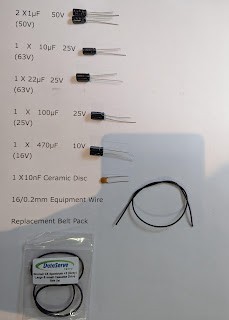
You will
also need the following components
7 pin DIN
Plug
3.5mm
Stereo (or mono) jack plug
2.5mm
Mono Jack plug
Stereo
speaker cable (I used an old PS2 composite cable)
And all
the relevant tools to solder the wires to the connectors
Here is my wiring diagram
Here is the wired 2.5mm Mono Jack Plug
Here is the wired 3.5mm Stereo Jack Plug
Here is the wired 7 Pin DIN Plug
And here is the completed cable
Time to test EVERYTHING!
Firstly, set up the Acorn Electron
Note that the TZX Duino will work with a mini USB Cable plugged directly into the Arduino Nano
Plug the 7 Pin DIN Plug into the Cassette port
Type
CHAIN""
Then press
RETURN
On the Electron
Now we need to select a file to load; as I put all the ROM
Set on to my SD Card in alphabetical folders I have to do the following key
presses on the TZX Duino (see Video)
Select the letter folder by pressing either the UP or DOWN
buttons
Once you have found the correct folder press the PLAY button
to enter that folder
Select the game in the folder by pressing either the UP or
DOWN buttons
Finally press PLAY
And that should start loading the UEF
Hopefully the UEF file will load correctly and you will be enjoying some 1980's Electron fun!
Success! Another working machine!
Here is the Youtube Video of the whole process
The Acorn Electron is a fantastic piece of hardware; I loved
every single minute spent working on it! It was also pleasing to
introduce my 8 year old #Apprentice_Geek. His soldering skills have improved
greatly since his first attempt… Thank
you my young apprentice!
Other people to thank are the very knowledgeable folks at


Comments
Post a Comment