Repair and restoration of retro consoles, 8 bit computers. In this blog I hope to show you how to repair, retrore and modify old consoles and handhelds, from manufacturers such as Atari Amstrad Acorn Sinclair Commodore Dragon Sony MSX BBC Playstation Sega Microsoft xbox Spectrum ZX81 Vic 20 VIC20 C64 Amiga Binatone Grandstand.
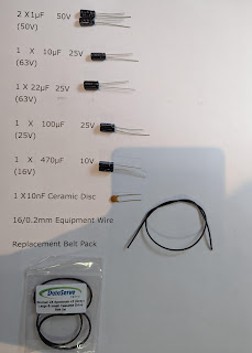
Apologies for the delay with this entry; varied reasons include school holidays, two birthdays and some minor repairs of some retro console birthday gifts! Please feel free to use my PCB and 3D printed housing designs found on my Github and Thingiverse should you wish to make your own joystick adapter. Here is the TI994a working with the FlashRom99 and my Joystick Adapter circuit. Here are all the components required for this mod. The gerber files for my PCB design can be found on my Github. https://github.com/Alleged-Geek/TI99-4a-Joystick-Adapter/ And you are looking for the zip file named below if you are going to send the gerber file off to be manufactured. ti99-4a-adapter_2022-07-27.zip My github also contains stl files for printing the housing. And here is my version of the schematic diagram. You will need 10 X IN4148 signal diodes which can be found on eBay. 1 X DB9 D-SUB 9 Pin Female connector, again found on eBay. 2 X DB9 D-SUB 9 Pin Male connector al...
Get link
Facebook
X
Pinterest
Email
Other Apps
ZX81 Composite Video Mod and Restoration
Issue One ZX81 Restoration and Composite Video modification.
This is my second entry and it wasn’t quite as
straightforward as I hoped it would be.
Here is a little background; I won a ZX81 with 16k Ram Pack
and a load of ZX81 books at auction, at just
under £20 in total it was a very good price. As it was a proper auction and not ebay I had no idea if the ZX81
would actually work or indeed what kind of state it was in.
Saying that, as I already have an issue one ZX81 already in
my collection I wasn’t really that bothered as the books and ram pack alone
would have set me back over £20 on ebay. Confirmation came through that I had
won the little computer and I couldn’t wait to get my grubby little paws on it!
After picking it up, it looked to be in better shape than
the one I already had in my collection!
below is a photo of my haul from the auction house.
Before I plug anything in to the mains, I always check the
plug… I am so glad I did as I was greeted with this monstrosity
There is so much wrong with this image
1 -
the cord grip is loose
2 -
the cable has a piece of foam to try and secure
it in place (if the previous owner had the cord grip the right way up then
there would be no need for that dangerous strip of foam)
3 - if you look closely enough you will see that the
neutral has been crushed on the centre boss for the securing screw
4 - both the live and neutral wires are the same
length
5 - there is bare wire showing on both the live and
neutral terminals
6 - there is a 13A fuse fitted!
7 -
Although you can't see it, and as the plug was
very old it didn’t have the insulators on the live and neutral pins.
Phew rant over
Here is what it should look like
New plug fitted and voltage checked on the 3.5mm mono jack
plug. It read 12VDC with the positive on the tip of the jack plug.
Time for some fun now…
I plugged it in and it powered up, albeit with a pretty poor
picture on my TV. I then tried to load a game using my TZX Duino, this was
problematic, it should have worked (as it worked for my other ZX81) but wasn’t keen to load. I had a similar
problem with my older ZX81 and it turned out to be a faulty ear socket which I will
go into more detail about later on. Finally after a bit of tinkering I managed
to load a game, but just look at the picture!
Horrible! No synch and pretty fuzzy… time to sort this out.
I was impressed by the price, quality and speed of delivery,
he even threw in a worthers original (which my 8 year old intercepted before I got the chance to enjoy)
I briefly mentioned earlier about the problem loading games
and my solution last time was to replace the 3.5mm mono ear jack socket (I
actually replaced all three sockets in truth) they tend to corrode over time
and I found that the contacts were loose from many years of use.
I had a dig around in my old connectors box and found a bag
full of similar connectors, after a wee bit of modification they would work
just fine.
All I really had to do was to cut a pin off the front right
of each jack socket.
These connectors are probably as old as the originals
(showing my age and hoarding skills here) but after a little brush with a fibre
pen they came up quite nicely.
Next up was to remove the old jack sockets and modulator.
As usual, desoldering
a plated through hole circuit board proved to be problematic. A wee tip is to
add fresh solder to the desoldered joint then desolder again until all the
solder has been removed. Take care doing this as the traces are easily damaged
as I will show you later.
There was a fair bit of flux residue left on the circuit
board so after a wee scrub with the Mrs’s toothbrush and some 99% ipa it turned
out quite nicely.
Now let’s have a look at that modulator
There are a couple of ways to fit the composite circuit
One way is to simply remove the video in, ground and video
out wires from the modulator and house the board outside the modulator.
And the other which I opted to do was to remove all the circuitry
inside the modulator (storing it away safely should I decide to restore the
ZX81 back to its original state) and fit the PCB into the modulator housing.
Care should be taken when removing the circuit board, it is
soldered on to the case of the modulator housing and it took quite a while and
a higher temperature setting on my soldering iron to finally remove all the
solder so that the PCB fell out the bottom (after a wee bit of persuasion)
Before fitting the pcb make sure that you fit
the insulator on the bottom of the modulator as without it you will run into
all sorts of problems. Below is a photo of the PCB fitted inside the modulator.
The ground is soldered on to the chassis, the +5V and Video
in are fed through the two white plastic bushes and the Video out is soldered on to the RF
socket onto which a standard phono plug fits extremely well.
Time to start soldering on to the ZX81 PCB
First up the 3.5mm mono jack sockets
These need to be sitting as flat on the circuit board as
possible so a wee tip is to solder two opposite legs then check that the socket
is seated correctly. If not then simply heat the solder on the raised side and push
the component flat against the circuit board.
The composite modded modulator was next
Unfortunately this is where my troubles started!
The trace leading to the +5V via lifted when I removed the
original wire so I had to carefully repair the damage done. Using tweesers I
was able to hold the lifted trace down whilst I soldered the +5V wire on to
both sides of the via. Not the best repair I have ever done but it got the job
done, I tested the repair with my multimeter just to be on the safe side.
Here is a wiring diagram showing the solder points on a
blank ZX81
Here are the solder points on my ZX81
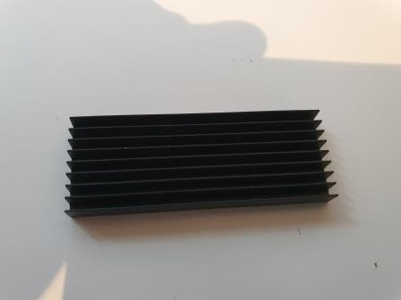
Next up was to fit the heatsink, I used some thermal paste
as shown and firmly fitted the heatsink to the ULA which tends to overheat
(especially when the 16k Ram Pack is fitted)
Now all I had to do was to fit everything back together
again.
This is when another little problem arose and I am at a
complete loss as to how this happened or what actually happened to the
connector in question.
When I went to fit the keyboard membrane to the connector on
the ZX81, the 8 pin connector held the keyboard membrane snugly and was a good
fit. However… the 5 pin connector just wouldn’t hold the membrane. Time to
investigate…
It appeared to be missing half of the metal clips which
meant that the membrane was never going to connect. I pulled a pin out and sure
enough, half the connector was missing! This one has beaten me, I have
absolutely no idea what went wrong as nothing fell out of the connector when I
removed the membrane.
I found replacement connectors on www.sellmyretro.com for £5.40 including
shipping. Like Mutant Caterpillar I was very impressed by the quality and speed
of delivery, and for a reasonable price as well .
Below is a picture of the broken and new connector
I just had to fit it now
Before I fitted the keyboard membrane, I decided to clean up
the edge connector with some 99% IPA, I was quite pleased with the result. (Mrs Geek probably not so pleased with the state of her toothbrush though ;))
After fitting the membrane, I screwed the case together for
testing… unfortunately my problems with the keyboard weren’t completely solved
as some of the keys weren’t working. Time to check the ZX81 schematic diagram for some clues...
Here is the schematic for the keyboard matrix; highlighted red were the non functioning keys so it was realtivley easy to trace the fault back to the 5 pin connector.
Sure enough, there was a hairline fracture on one of the
silver traces on the membrane. As this was close to the end that fits into the
socket I simply used a pair of scissors to cut off the damaged part (when doing
this try and get as straight a cut as possible). Luckily for me the membrane
was still long enough to fit.
Time to put everything back together… hopefully for the last
time!
I crossed my fingers, held my breath and turned the computer
on…
After testing all the keys, I decided that I would try and
load up a game from my own version of the TZX Duino to test the intermittent
fault when loading the games
And…
Success! Loaded first time and with a stable image on the TV
screen!
Like the Binatone, I have had so much fun restoring this iconic
computer from the early 80’s Granted this restoration wasn’t straightforward,
but that is where my enjoyment and love of restoration comes from… you never
know what you are going to get!
If you have any questions or queries or if you would like
the gerber files of my PCB design then please feel free to get in touch


Comments
Post a Comment